


Industrial LCD Panel
-
Payment


-
Origin
China Mainland
-
Minimum Order
5
-
Packing
Pieces
- Contact Now Start Order
- Description
Product Detail
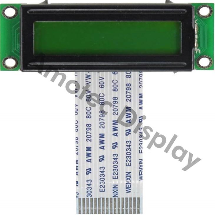
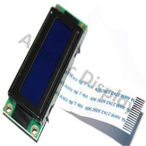
Industrial LCD panel
Industrial LCD panel ADM1602N
Model No. ADM1602N
?Industrial LCD panel
?Character LCD
?5 x 8 dots includes cursor
?Built-in controller ST7066
?5V/3.0V power supply
?1/16 duty cycle
Description of industrial LCD panel ADM1602N
Amotec Display provides you with the toughest industrial LCD panel available in the industry. We offer industrial LCD panel with your choice of mounting options that are capable of operating under extreme conditions such as heat, sunlight, and dust as well as in the presence of corrosive elements.
Features
1.5x8 dots
2.Built-in controller (ST7066 or equivalent)
3.+5V power supply (also available for =3.0V)
4.1/16 duty cycle
5.Easy interface with 4-bit or 8-bit MPU
6.BKL to be driven by pin1, pin2, or A, K
7.16x2 characters
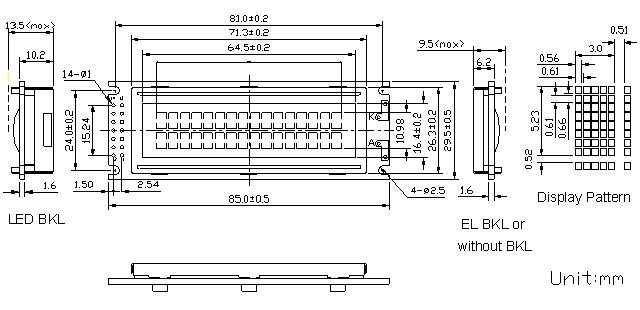
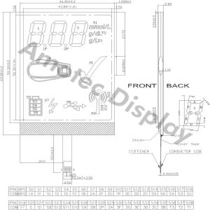
Outline dimension
Absolute maximum ratings
Item | Symbol | Standard | Unit | ||
Power voltage | VDD-VSS | -0.3 | - | 7.0 | V |
Input voltage | VIN | -0.3 | - | VDD+0.3 | |
Operating temperature range | Top | 0 | - | +50 | ? |
Storage temperature range | Tst | -10 | - | +60 | |
*Wide temperature range is available
(operating/storage temperature as –20~+70/-30~+80?)
Block diagram
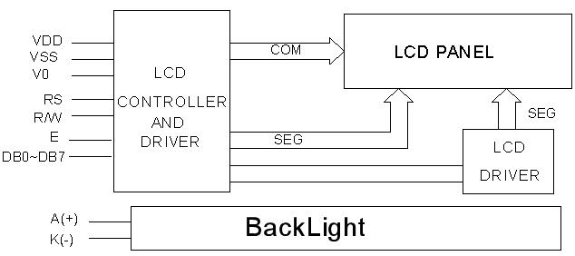
Interface description
Pin no. | Symbol | External connection | Function |
1 | VSS | Power supply | Signal ground for LCM (GND) |
2 | VDD | Power supply for logic for LCM | |
3 | V0 | Contrast adjust | |
4 | RS | MPU | Register select signal |
5 | R/W | MPU | Read/write select signal |
6 | E | MPU | Operation (data read/write) enable signal |
7~10 | DB0~DB3 | MPU | Four low order bi-directional three-state data bus lines. |
11~14 | DB4~DB7 | MPU | Four high order bi-directional three-state data bus lines. |
| A(LED+) | LED BKL power supply | Power supply for BKL (Anode) |
| K(LED-) | Power supply for BKL (GND) |
Contrast adjust
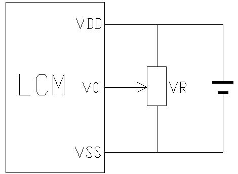
VDD~V0: LCD Driving voltage
VR: 10k~20k
Optical characteristics
TN type display module (Ta=25?, VDD=5.0V)
Item | Symbol | Condition | Min. | Typ. | Max. | Unit |
Viewing angle | ? | Cr=4 | -25 | - | - | deg |
F | -30 | - | 30 | |||
Contrast ratio | Cr |
| - | 6 | - | - |
Response time (rise) | Tr | - | - | 120 | 150 | ms |
Response time (fall) | Tr | - | - | 120 | 150 |
STN type display module (Ta=25?, VDD=5.0V)
Item | Symbol | Condition | Min. | Typ. | Max. | Unit |
Viewing angle | ? | Cr=2 | -60 | - | 35 | deg |
F | -40 | - | 40 | |||
Contrast ratio | Cr |
| - | 8 | - | - |
Response time (rise) | Tr | - | - | 200 | 250 | ms |
Response time (fall) | Tr | - | - | 300 | 350 |
Electrical characteristics
DC characteristics
Parameter | Symbol | Conditions | Min. | Typ. | Max. | Unit |
Supply voltage for LCD | VDD-V0 | Ta =25? | - | 4.6 | - | V |
Input voltage | VDD |
| 4.7 | 5.0 | 5.5 | |
Backlight supply voltage | VF |
| - |
| - | |
Supply current | IDD | Ta=25?, VDD=5.0V | - | 1.5 | 2.5 | mA |
Input leakage current | ILKG |
| - | - | 1.0 | uA |
“H” level input voltage | VIH |
| 2.2 | - | VDD | V |
“L” level input voltage | VIL | Twice initial value or less | 0 | - | 0.6 | |
“H” level output voltage | VOH | LOH=-0.25mA | 2.4 | - | - | |
“L” level output voltage | VOL | LOH=1.6mA | - | - | 0.4 |
Read cycle (Ta=25?, VDD=5.0V)
Parameter | Symbol | Test pin | Min. | Typ. | Max. | Unit |
Enable cycle time | tc | E | 500 | - | - | ns |
Enable pulse width | tw | 230 | - | - | ||
Enable rise/fall time | tr, tf | - | - | 20 | ||
RS; R/W setup time | tsu | RS; R/W | 40 | - | - | |
RS; R/W address hold time | th | 10 | - | - | ||
Data output delay | td | DB0~DB7 | - | - | 120 | |
Data hold time | tdh | 5 | - | - |
Write cycle (Ta=25?, VDD=5.0V)
Parameter | Symbol | Test pin | Min. | Typ. | Max. | Unit |
Enable cycle time | tc | E | 500 | - | - | ns |
Enable pulse width | tw | 230 | - | - | ||
Enable rise/fall time | tr, tf | - | - | 20 | ||
RS; R/W setup time | tsu1 | RS; R/W | 40 | - | - | |
RS; R/W address hold time | th1 | 10 | - | - | ||
Data output delay | tsu2 | DB0~DB7 | 80 | - | - | |
Data hold time | th2 | 10 | - | - |
FAQ
1.Comparison between STN LCD and TFT displays?
STN LCDs require less power and are less expensive to manufacture than TFT LCDs, another popular type of LCD that has largely superseded STN for mainstream laptops. STN displays typically suffer from lower image quality and slower response time than TFT displays. However, STN LCDs can be made purely reflective for viewing under direct sunlight. STN displays are used in some inexpensive mobile phones and informational screens of some digital products.
2.What are the Installing Precautions
The hole in the printed circuit board is used to fix LCM as shown in the picture below. Attend to the following items when installing the LCM.
(1)Cover the surface with a transparent protective plate to protect the polarizer and LC cell.
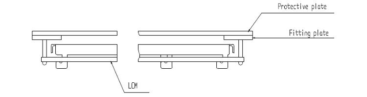
(2)When assembling the LCM into other equipment, the spacer to the bit between the LCM and the fitting plate should have enough height to avoid causing stress to the module surface, refer to the individual specifications for measurements. The measurement tolerance should be 0.1mm.
3.What is the difference between COG and COB ?
COG LCD modules can be more compact, reliable, cost effective, and require a lower currency than COB LCD modules.
4.How long can we expect the samples?
Answer: Most of the time, we have samples in stock. If not, it only take 1-2weeks for us to get samples ready.
-
TFT LCD 7 Monitor 5 Pieces / (Min. Order)

-
Graphic LCD Smart Display 5 Pieces / (Min. Order)

-
High Contrast LCD Display 5 Pieces / (Min. Order)

-
LCD Graphic Display 128x64 5 Pieces / (Min. Order)

-
Low Power LCD Display 5 Pieces / (Min. Order)

-
Character LCD Display Panel 5 Pieces / (Min. Order)

-
Digital LCD Display 5 Pieces / (Min. Order)
-
Monochrome LCD Display Module 5 Pieces / (Min. Order)

-
Parallel Graphic LCD Display Module 5 Pieces / (Min. Order)

-
Graphic COB LCD Module 5 Pieces / (Min. Order)

-
COB LCD Module 5 Pieces / (Min. Order)
-
LCD Graphic Smart Display 5 Pieces / (Min. Order)

-
Graphic LCD Display Module 5 Pieces / (Min. Order)

 Favorites

-
TFT LCD 7 Monitor
5 Pieces / (Min. Order)
-
Graphic LCD Smart Display
5 Pieces / (Min. Order)
-
High Contrast LCD Display
5 Pieces / (Min. Order)
-
LCD Graphic Display 128x64
5 Pieces / (Min. Order)
-
Low Power LCD Display
5 Pieces / (Min. Order)
-
Character LCD Display Panel
5 Pieces / (Min. Order)
-
Digital LCD Display
5 Pieces / (Min. Order)
-
Monochrome LCD Display Module
5 Pieces / (Min. Order)
-
Parallel Graphic LCD Display Module
5 Pieces / (Min. Order)
-
Graphic COB LCD Module
5 Pieces / (Min. Order)
-
COB LCD Module
5 Pieces / (Min. Order)
-
LCD Graphic Smart Display
5 Pieces / (Min. Order)
-
Graphic LCD Display Module
5 Pieces / (Min. Order)